Friday, 2 August 2019

Leather work

Apprehension has relegated this particular task to the final stages of the build. I have never undertaken any leather work before and had subconsciously delayed the work in preference to more familiar jobs, an avoidance tactic perhaps! but now there were no more excuses, I had to get on with it.

A few weeks previously I had purchased a Speedy Stitcher and a spool of buff waxed heavy polyester thread, armed with the instruction leaflet that came with the tool, I proceeded to practice the process before committing to the real thing. To my surprise I got the hang of it in around an hour and proceeded to stitch the protective leather sleeves onto the oars.  I first wrapped the leather around the oar and held it in place with clamps whilst marking the point at which the two ends overlapped, I then removed the material and trimmed back the edge approximately 6 mm from the mark, this produced an open joint which would be closed when the leather was stitched and stretched.  I then marked out the stitching centres and pierced the leather to assist the penetration of the Speedy Stitcher needle. Working along the joint for approximately 50 mm, I kept moving back to tension the thread by lifting each loop with a small screwdriver before continuing. A good result was achieved with a traditional classic look.


The Speedy Stitcher in action.


One down one to go!

There were two other surfaces that I considered would require protection, the notch in the transom for the sculling oar and the base of the gaff jaws that come into contact with the mast. I marked out and cut patterns on thin card to arrive at a suitable design, giving due consideration to allow enough relief in the profile to enable me to stretch the leather over the curved surfaces to achieve a tight fit. Before fitting, I soaked the leather in water to make it more pliable then stretched it onto the surfaces held temporarily in place with clamps. I used a large spoon to shape the leather tight onto the contours then finally fixed in place with copper tacks. Again a result, that looks both decorative and functional.


Finally I considered it prudent to fit a protective leather sleeve around the bowsprit at the point where it passes through the bowsprit iron at the stem head; this will protect the timber and provide a nice snug bed between the timber and the bronze ring.


Wednesday, 31 July 2019

Painting Varnishing and Fitting Out

I have somewhat neglected the blog over the past few months, my priority being focused on the build instead, and as usual I have been giving the project my undivided attention by continuing to put in as many hours as possible. I have previously alluded to the fact that the amount of work and materials required for the painting/varnishing has surprised me and has continued to do so in these final stages. Following meticulous preparation I have applied five or six coats, rubbing down between each with a very fine grade abrasive paper followed by fine steel wool before vacuuming thoroughly then removing the really fine dust particles with Tack cloths. A temporary plastic sheet was suspended above the whole project to minimise the risk of any potential dust or other debris falling from the roof of the barn which, would have contaminated the work. On the whole I’m pretty pleased with the results that I have achieved thus far, however I have resolved to improve the finishes still further with additional coats planned during future maintenance following each season of use.

Sealant has been applied to all mating surfaces of the fittings passing through or fitted to the surface of the vessel to prevent water ingress, therefore minimising the risk of rot and decay setting in between the two surfaces.

I have been continuing the installation of the wiring and equipment including installing a Simrad Cruise 7 Chart Plotter with a transom mounted transducer for monitoring depth and bottom imaging, running on C-Map Cartography.

Research and subsequent meetings have been undertaken with regard to the trailer, sails and berth mattresses, all of which have been ordered with delivery expected imminently.


The auxiliary fuel tank sited in the starboard locker has been connected and the engine alternator has been wired to a detachable waterproof plug sited on the port side.

Monday, 20 May 2019

Laying the Teak Deck – Toe Rails


Because of the challenges I have faced in producing a deck to satisfy my perceived design requirements, it has been quite some time since my last post, however  I can now report that the deck has been laid, caulked and rubbed down.

Since the start of the build, I have visualised how I wanted the deck to look and invested some time in marking out the layout in chalk, this allowed me to make adjustments in the design by simply rubbing off any offending lines to alter the set out. I felt it absolutely essential that the teak strips be swept to follow the lines of the boat with the exception of the deck forward of the cabin which, I laid parallel to the sides of the anchor compartment cover.

The amidships area around the cabin required the teak strips (45mm x 6mm) to be bent to a fairly tight radius. At first I tried to achieve this by cold bending, but found that the radius was beyond the limit from which they were prepared to bend. Following further research I discovered that there were conflicting views as to whether teak could be steam bent, especially given that the strips required edge bending in the horizontal plane with the 45mm face uppermost. I decided to build a steam box and a jig constructed to the appropriate radius. Despite multiple attempts by varying the time the material spent in the steam box, I could not achieve the required radius without the material buckling, even by using a system of multiple clamps to hold the strips flat to the jig base. I concluded that the only option was to purchase some additional wide boards and cut each individual deck strip to the required radius; this proved to be time consuming and produced a high percentage of waste material, however I achieved the results I aspired to. The teak strips were glued down with epoxy as I had done previously with the cockpit sole. The 5mm wide joints were then primed with Sika Flex 290 DC primer before filling with Sikflex 290 DC Pro in black. I allowed about three weeks for the product to fully cure before sanding the surface off flush. Time was occupied during the interim period by painting and varnishing completed surfaces.


The steam box. I constructed the steam delivery pipe in 15mm copper tube with
soldered fittings then used insulation to minimise temperature drop  


Edge bending a teak planking strip.  I did achieve a gentle bend to this aft plank:
Note the timber strips screwed through into the jig base to prevent buckling


You can see the tighter radius amidships


The aft set out


I put the steam box to good use to steam bend the sapele toe rails. Following two hours in the box, they bent easily around the jig. I over compensated the radius to allow for spring back when they were removed from the jig the following day.


Steam bending the toe rails. I manufactured them to the finished tapered
profile then cut corresponding tapered blocks for the jig


Completed teak decking and toe rails.


Sunday, 31 March 2019

Oars


I had intended that my next post be the laying of the teak deck; however this has been delayed because of challenges that I will allude to in due course. In the meantime this interim post regards the construction of the oars, yes the plural! Francois Vivier’s design included just one sculling oar to be carried aboard Beniguet, but as I have previously stated in my post last December, I have fitted rowlocks to give me the option of rowing. The drawings give the dimensions only, with no recommendation as to their construction. I concluded that they would be structurally more stable and stronger if made up in four pieces. I used ash as recommended, grooving the mating faces and inserting a tongue throughout, after gluing with epoxy they produced a solid structure. They were then shaped down to the design profile by chisel and plane then, again making good use of my home made mast sanding tool, I rounded the shafts or looms. Following varnishing, a leather sleeve will be stitched to the looms for a wearing surface and protection against the rowlocks or transom notch.


This shows how I jointed the blades of the oars with the shaft or loom, 
tapered to a point rather like a cricket bat.


Glued up prior to shaping


The finished articles. Note the sheathed tips to reinforce the ends to prevent splitting or damage.
The other item to the right is a seat for rowing, this will span the cockpit.

Monday, 11 February 2019

Mast and Spars


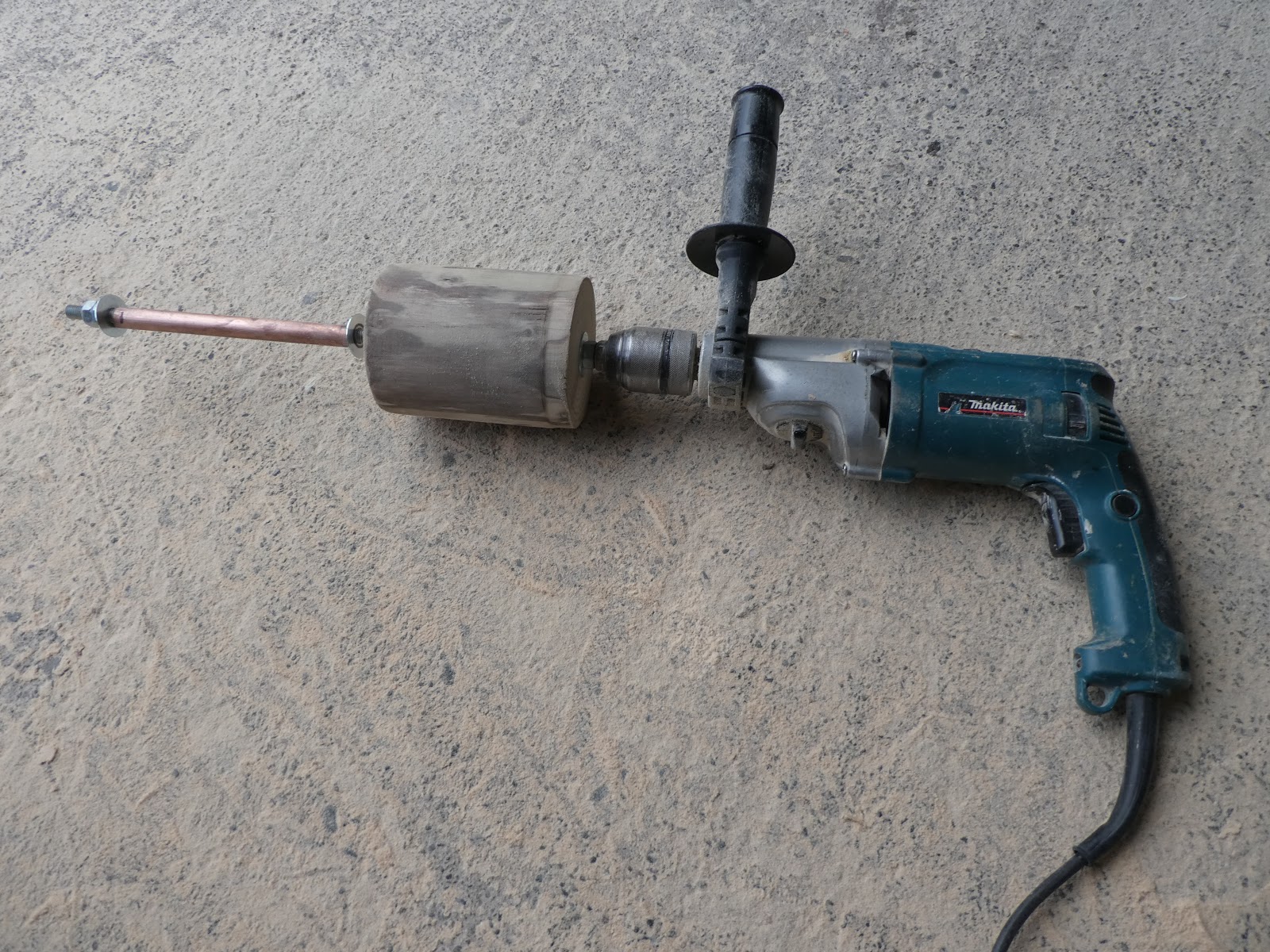
My blog 31st July 2018 described the laminated manufacture of the mast. I deliberately constructed it during the summer months to take advantage of the warm weather to aid the penetration of the epoxy into the fibres of the timber, it was then machined square to size and set aside. I have been looking forward to continuing the process of rounding and finishing along with the manufacture of the boom, gaff and bowsprit. I first planed down the correct taper in its square form before marking with a spar gauge then planning off the corners to form an octagon. I then continued to work it round with the plane and then abrasive paper on a block with a rotating action when pushing the block along its length, however, I found it time consuming and considered the results less than acceptable, I decided that I needed mechanical assistance. My solution was to manufacture a timber cylinder with a hole bored down its centre to allow a threaded stud to be inserted, nuts and penny washers were fitted either side to secure the cylinder allowing an approximate 40 mm projection on one side and 200 mm on the other. I then slid over a length of 15 mm copper tube and secured it loosely with two locking nuts at the end to allowing free rotation . The contraption was then secured in an electric drill chuck with the drill speed set low. I then inverted a sanding belt, thread it over the mast, inserted the rotating cylinder and applied tension to drive the belt by friction, unfortunately the belt refused to rotate around the mast but sanded the cylinder instead! I realised that I needed to increase the diameter of the cylinder to greater than that of the mast for the rig to work, I therefore re-constructed the rig with a lager diameter cylinder and tried again. Success, it worked wonderfully well and I was able to produce a beautifully round mast by roughing it down with a coarse grade before progressively using finer papers to achieve a smooth finish.


My home made mast rounding tool.


In action.


Dust flying everywhere, result!


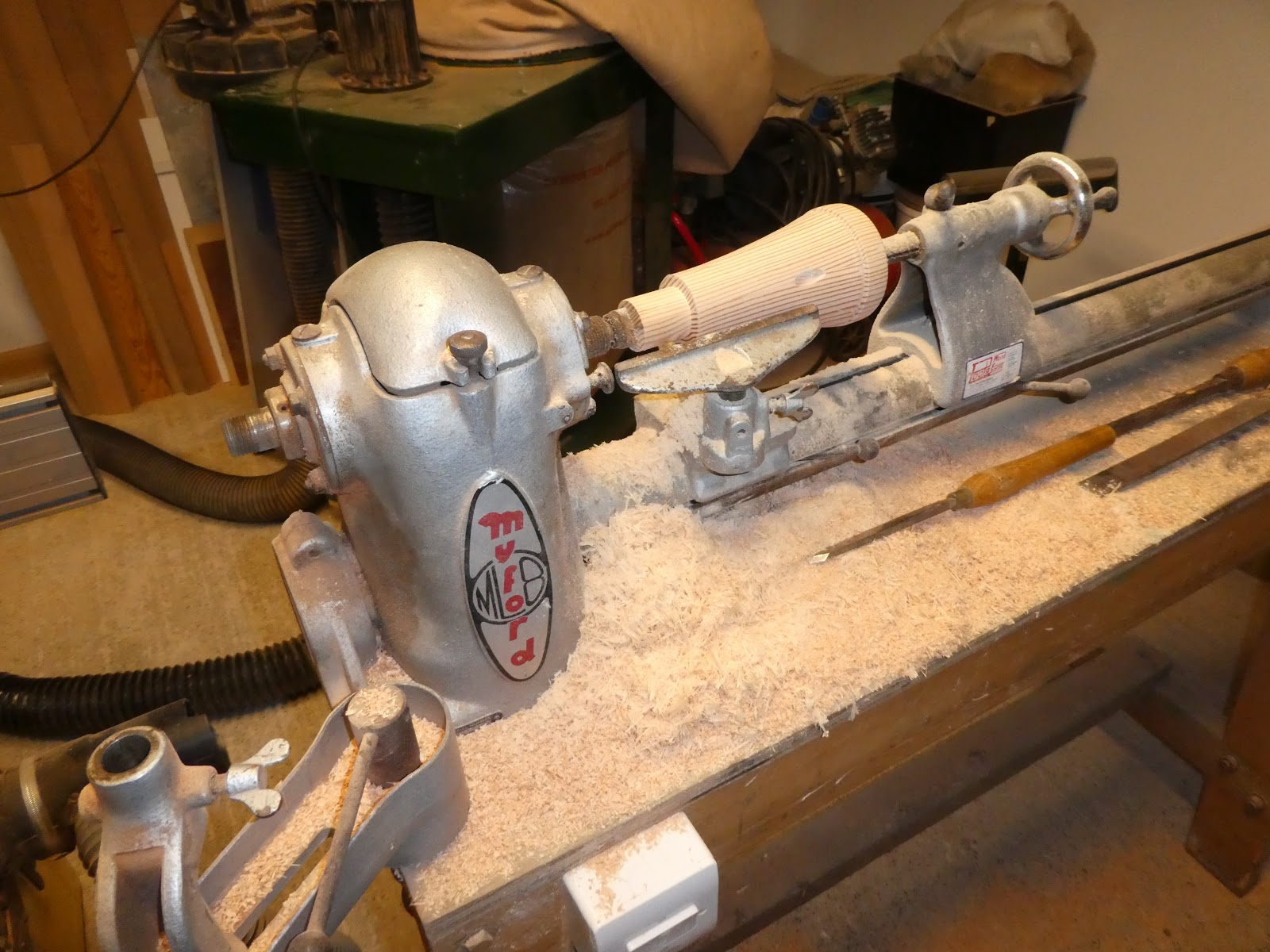
Because of my intention to fit navigation lights and a VHF antenna, I customised the head of the mast to accommodate an LED Tri-Colour and antenna bracket. It was necessary to increase the 50 mm diameter mast head to 90 mm, I therefore made up two blocks with a half round machined into each face, when glued together they would then form a 16 mm diameter duct for the cables. In the lathe I turned the block down to an aesthetically pleasing profile then turned on a 30 mm diameter spigot and shoulder which would fit in to a corresponding hole bored in the mast head. The cables were pulled through the whole mast assembly prior to gluing, due care was taken to ensure that the epoxy did not squeeze out internally into the duct, therefore preventing potential cable replacement at a future date. 


The two blocks with half round ducts machined into each face.


The finished mast head ready for release from the lathe.


The architects designed masthead incorporates a 10 mm diameter hole drilled through approximately 40 mm down from the tip, the peak halyard passes through and is secured by a knot tied in the end. I was unable to adhere to this because of my cable duct throughout the mast; I therefore fitted an additional two eye mast hound which also provided me with a potentially useful spare forward facing eye. Both of these hounds were bedded onto the mast in epoxy mixed with fibres, to prevent possible rotation, a bronze countersunk screw was inserted either side of each hound. To prevent potential rotation of the main four eyed mast hound, I filed half round grooves into the inner face, sheathed around the mast then bedded the hound in epoxy onto the sheathing.


Because I have opted for a roller furling jib, the forestay is attached to the mast by means of a loop which, is prevented from sliding down by a wooden block. I considered that with this design there was a potential for the wire stay to wear around the mast, I therefore sheathed this area to provide a tougher wearing surface. I also saturated the base of the mast in epoxy and gently warmed it through with a heat gun to assist its penetration into the grain; this I hoped would toughen the fibres of the wood and provide a harder wearing surface against the steel tabernacle.


The completed mast and spars showing the additional two eye mast hound
VHF antenna and Tri-Colour navigation/anchor light. The base and the upper
reaches of the mast above the four eye hound will be painted white,
all other areas and spars will be clear varnished.


The base of the mast saturated in epoxy, teak cleat fitted to the fore face 
for the jib halyard.


The gaff jaws all laminated, clamped up, set and ready for release.


The manufacture of the gaff jaws was an interesting and enjoyable exercise.
This structure consumed the last of my home grown ash.


The boom gooseneck.


Work began on the build 12th February 2017. Today is the day I have been working on the boat for two years and has so far consumed 1,968 man hours. Onwards and upwards, the finish is just peaking above the horizon!


Tuesday, 22 January 2019

Companionway Hatch - Panels and miscellaneous items


In one of my previous posts  Manufacturing Items In The Workshop March 2018, you will see that I had constructed the sliding hatch, however the manufacture and fitting of the various other component parts that make up the sliding stocks and panels that close off the companionway, proved to be very time consuming. I decided to use nylon runners screwed to the hatch sides as opposed to hardwood; my train of thought considered that the contact between the differing materials would result in less friction and therefore a reduced likelihood of wear between these and the sliding stock grooves.

There are hardwood inner and outer guides fixed to either side of the companionway bulkhead that form grooves for the panels to sit in, however I considered that there would be a potential problem of water collecting and flooding the lower groove. My solution was to glue in a thin insert of hardwood into the bottom, the profile worked to direct the water towards two drainage slots cut in the aft face of the bottom guide.

You will see from previous posts that I have panelled the aft face of the companionway bulkhead in sapele, I had for some time mulled over in my mind that the outer face of the companionway panels might look aesthetically unappealing if painted; this became immediately apparent once they were slotted into place. I therefore continued the hardwood boards onto the plywood panels, taking care to line through the grooved joints to maintain continuity.


Note the drainage slots cut into the bottom guide


The companionway panels in place. I plan to fit a bronze star
 in the centre of the featured upper panel (for good luck!)

Other work undertaken included the fitting of the rudder, mainsheet  transom horse, constructing a platform in the starboard locker to support the auxiliary fuel tank complete with retaining straps and a plug in point for the motor alternator wiring feed to the battery to allow quick disconnection and removal of the motor.

To achieve a professional looking fuel tank installation, it was necessary for the fuel delivery pipe to pass through the bulkhead forming the aft face of the locker. To maintain its water tightness, I fitted a rubber bellow Witches Hat, the sort of thing you would commonly see fitted to a steering wheel or a gear stick, this provides an excellent neat looking flexible seal.  


Note on the port side the alternator plug in point for battery charging 


The stowed auxiliary fuel tank showing the Witches Hat 
for the fuel delivery pipe

Sunday, 2 December 2018

Coach Roof Coamings and Trims


The amount of timber consumed by the build continues to surprise me, pretty substantial rough sawn boards are regularly purchased, sawn and planned to size in my workshop before disappearing into the boat, leaving one wondering where it’s all gone. The coach roof and coaming trims are a case in point, requiring a number of seemingly minor lengths of timber which collectively forms a fair bit of material. The geometry of the cabin and coamings call for quite a bit of bending and twisting of materials to form the composite shapes and lines, you therefore need plenty of cramps available for use.

The cabin coamings are fitted with oval deadlights, specified are two flat bronze rings bolted either side of the coamings and glazed in Plexiglass sandwiched between. I have slightly modified this by substituting the inner ring for one made of sapele, this will be clear varnished along with the coamings. I manufactured these by machining a tongue and groove in two boards, when glued together they produced a single board of sufficient width to machine the rings from. To aesthetically harmonise with other components within the cabin, I machined an ovilo mould to the outer edge. The outer bronze ring is simply held in place by bronze wood screws passing through the plywood coaming into the inner hardwood ring.


On the forward end of the cabin coamings is an angled projection which, to my eye appeared too steep. I therefore requested when ordering the plywood for CNC cutting that this be extended further forward, thus decreasing the angle. I softened it further still by fitting a sapele cap tongued and grooved into the edge of the plywood.


Rubbing strakes and gunwales have also been fitted which, beautifully accentuates the sheer. As a decorative feature I machined a half round recessed mould into the centre line of the rubbing strakes before fading it out to a point around half a metre from the transom and stem respectively. I also carved a small scroll in the fore end between the fairlead and the stem, both of these features will be picked out in black paint before being clear varnished along with the gunwales and toe rails, all of which have been manufactured in sapele. 


I have begun screwing and bolting on the fittings for a dry run. They will all be removed before painting and varnishing then re-fitted with a sealant bed to prevent water ingress between the metal and the wood.


There are two hardwood blocks fixed to the outer face of the cockpit coamings, these provide a firm platform and fixing point for the jib sheet cam cleats. I have also fitted additional smaller blocks further aft to carry rowlocks. The boats transom is designed with a notch to accommodate a sculling oar, however I considered it might be useful to manufacture an additional oar and build in provision for rowlocks, this is a relatively light boat and oars could prove a useful addition. I wanted to minimise the visual impact of both of these blocks and chose to manufacture them with a radius at either end, this created an aesthetically pleasing shape inspired by the design of a capstan which, will hopefully provide additional interest to the build. I achieved this by building up either side of the block stock with sacrificial timbers glued and screwed to a plywood base; they were then worked in my wood turning lathe to achieve a cylindrical design of the appropriate diameter and thickness. When finished I simply cut away the sacrificial timber to reveal the profiled blocks within. 


The starboard blocks fitted to the cockpit coaming. 
Forward the jib sheet cam cleat and aft the rowlock. I have propped the jib sheet block to give an idea of its position.


Port side rowlock support block. The deck has been reinforced below both blocks either side.