Monday 30 July 2018

Mast Assembly


We have been experiencing a heat wave here in the UK which has greatly improved the viscosity of the epoxy and therefore its ability to penetrate the timber surfaces being glued. I have assumed that the mast will be subject to considerable forces in all directions and as such its structural integrity is paramount, I therefore saw this as an opportunity to construct the mast whilst the conditions were favourable. Rounding off and finishing can be done at a later date.

The architect recommends Douglas fir as a suitable species of timber for the mast and spars. Following prior consultation with my local timber merchants, I managed to obtain some top quality stock, perfectly true with a clear straight grain. I purchased sufficient for the whole job.

Handling 6 metre lengths of timber by oneself proved a little tricky, but I have a number of roller stands which proved essential. Four boards make up the laminated mast which I cut and planed dead true. Approximately three quarters of the mast is a hexagonal hollow. Because I have opted for navigation lights, VHF radio etc. I had to build in a duct/conduit to carry the cables to the mast head with the ability of pulling cables through at a later date if required. Through the solid sections I machined a 7 mm radius half round groove in each half then installed a plastic conduit supported in small plywood cradles down the centre of the hollow section. I was particularly careful to ensure there were no square edges to avoid any potential snagging during the process of pulling the cables through. During the gluing process I inserted a draw cord, when the mast was fully clamped up I tied a small piece of towelling onto the cord and pulled it through several times to remove the excess epoxy that had squeezed out into the duct. I continued this process at intervals during the curing time to be certain that the duct remained clear.
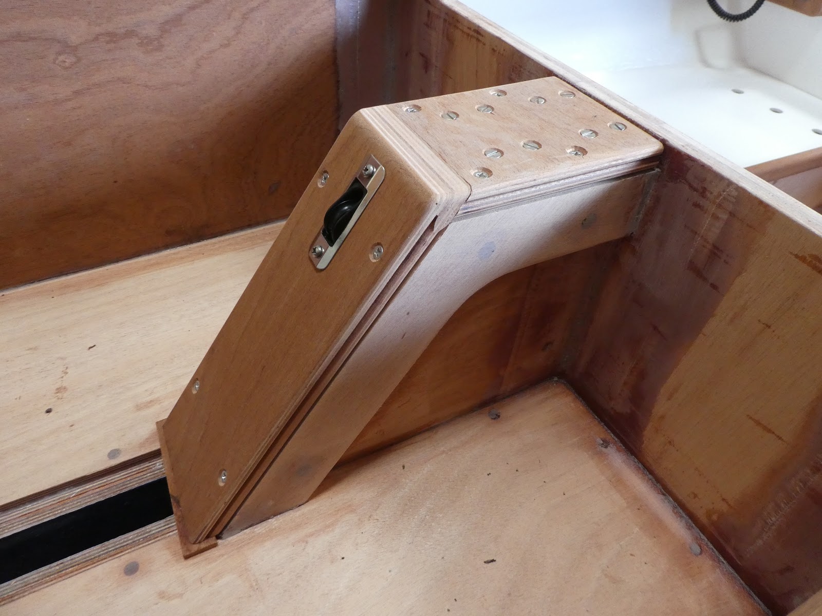


I have decided to terminate the cable duct just above the level of the Tabernacle. You can see that I have machined it in a slow curve to enable an easy cable pull through.


Note that I have recessed the plastic conduit into each end of the hollow section then rounded off the shoulder to prevent any snagging of the cables when pulling through.


Thursday 19 July 2018

Painting and Deck Fixing

It was necessary to paint as much of the boat as possible before the decks were fitted. As previously stated, many of the areas are difficult to access even before the plywood deck is fitted. I under estimated the cost of the painting materials and the time required to apply it, this proved to be both a costly and time consuming job to achieve the standard that I required.

I have used Hempel paints throughout the whole build. The coating regime for the internal painting began by applying Wood Impreg as a sealant, three coats of Primer Undercoat then three coats of Brilliant Gloss for visually exposed surfaces or three coats of Bilge and Locker paint where appropriate. I rubbed down de-dusted and cleaned between each coat. Sapele trims and other exposed hardwood items were sealed, again using Wood Impreg, before finishing with multiple coats of clear varnish. All the paint and varnish was applied with a range of specialist brush’s and roller, before laying off with a brush to finish.

The plywood deck panels were glued with epoxy and screwed down with countersunk stainless steel screws; any excess epoxy squeezed out below was removed and cleaned down with disposable paper towels. These areas will then only require a light rub down and the paint touching up. The screw heads were filled with epoxy filler. When set, the whole deck was rubbed down by an orbital sander to remove any irregularities whilst paying particular attention at the joints. The overhanging waste was trimmed back flush with the planking then a small pencil round radius was routed onto the corner. The whole deck was then sheathed in 300 gsm woven cloth and lapped over the edge onto the planking by approximately 30 - 40 mm. The small radius cut onto the top edge allowed the cloth to be dressed tightly over without any air pockets forming.


The areas to be glued were masked off before painting the underside of the deck boards.


The wiring has been installed whilst most areas are still relatively reasonably accessible. All cables and fittings are to specialist marine standards. The fixing brackets were fitted to the wiring conduit before the deck boards were fixed down, these will be stuck to the underside of the deck with self-adhesive double sided pads.

Tuesday 17 July 2018

Deck, Supporting Carlin’s and Beams

There has been a considerable amount of work that I felt was necessary to be carried out before the deck can be fixed in place. Carlin’s, beams and doublers act as support and reinforcement below the deck and inside the hull, and will allow additional strength for bolted through fittings, all these small but important items have required manufacture and fitting. Furthermore many of the areas are difficult to access particularly for painting, it’s therefore advisable to prepare and paint as many areas as possible before fixing the deck down.


Carlin’s, beams and reinforcing doublers all fitted and glued into place. The doublers are mainly 20mm thick laminated from two 10mm pieces of plywood. This reinforcement has been added to allow fittings to be bolted through, cleats, sheet leads, chain plates etc. There are also doublers beneath the butt joints of the deck.


I also prepared and dry fitted the whole deck plus the trim on the transom. I marked around the timbers below the plywood deck sections before removal, this allowed positioning of masking tape over the fixing areas to prevent contamination whilst painting the boards before fixing.  I took the opportunity of shaping the trim at the aft of the cockpit and inserted a central inlaid feature, deliberately cut from a different board of sapele to obtain a contrasting colour and grain structure, I further highlighted this with an inlay of ash around its perimeter to achieve further enhancement.

I have decided to finish the deck in teak planking set in epoxy with black Sikaflex joints. To assist in the design of the layout, I set out the planks in chalk to one half of the boat, this proved very useful to calculate the amount of planking required and was an easy way to alter the design by simply rubbing off the chalk with a damp sponge, I was then able to develop the set out until arriving at the most appealing design.


 Ash inlay, again as previously mentioned, as a nod to the tree I felled which has been used in the build.


Deck planking marked out in chalk


I decided to reinforce either side of the centre board case creating a broad edge for a more secure fixing for the capping’s. I laminated up two 10mm pieces of plywood then cut them to the shape shown in the photograph before gluing to the case. The capping’s I made from laminating two 10mm pieces of hard sepele faced plywood, then machined a bead in the edge to aesthetically improve junction with the case.


 Reinforcing pieces either side of centre board case and capping. The centre board hoisting system provided by Harken blocks mounted within the case have been fastened with stainless steel bolts which, will allow removal for future maintenance. These were removed before painting.


To accommodate an anchor of sufficient holding capability that would fit into the restricted space of the mooring and stowage well, proved to be an item of extensive research. I looked at every anchor design on the market and found that most would simply not fit, until I came across the Plastimo Kobra folding anchor. Research of this product revealed it to be an ideal solution, the folding capability allowed easy stowage with room to spare. Because of this I was able to raise the forward base of the well by around 50mm to allow better drainage towards the oblique to aft drilled holes through the hull planking, this also gave more room below. I sourced some small stainless steel shell vents to provide cover to the exposed holes on the outer face of the hull which looked very neat. The bottom of the well was filleted around its perimeter, sheathed in 300 gsm woven glass fabric saturated in epoxy, filled and faired to a smooth finish. Its planned to fit a protective rubber mat to the bottom minimise potential damage from the anchor and chain.


The Plastimo Kobra folding anchor neatly stowed in the well. The additional 20mm thick plywood reinforcing seen here beneath the deck, will provide solidity for bolted through fixings for mooring cleats, stemhead chain guide, bowsprit iron and lashing eye plates. You can also see the anchor cable fastening eye bolt.


The stainless steel shell vents can be seen covering the anchor and mooring stowage well drainage holes