Sunday, 4 November 2018

Laying Teak Planking to the Cockpit Sole


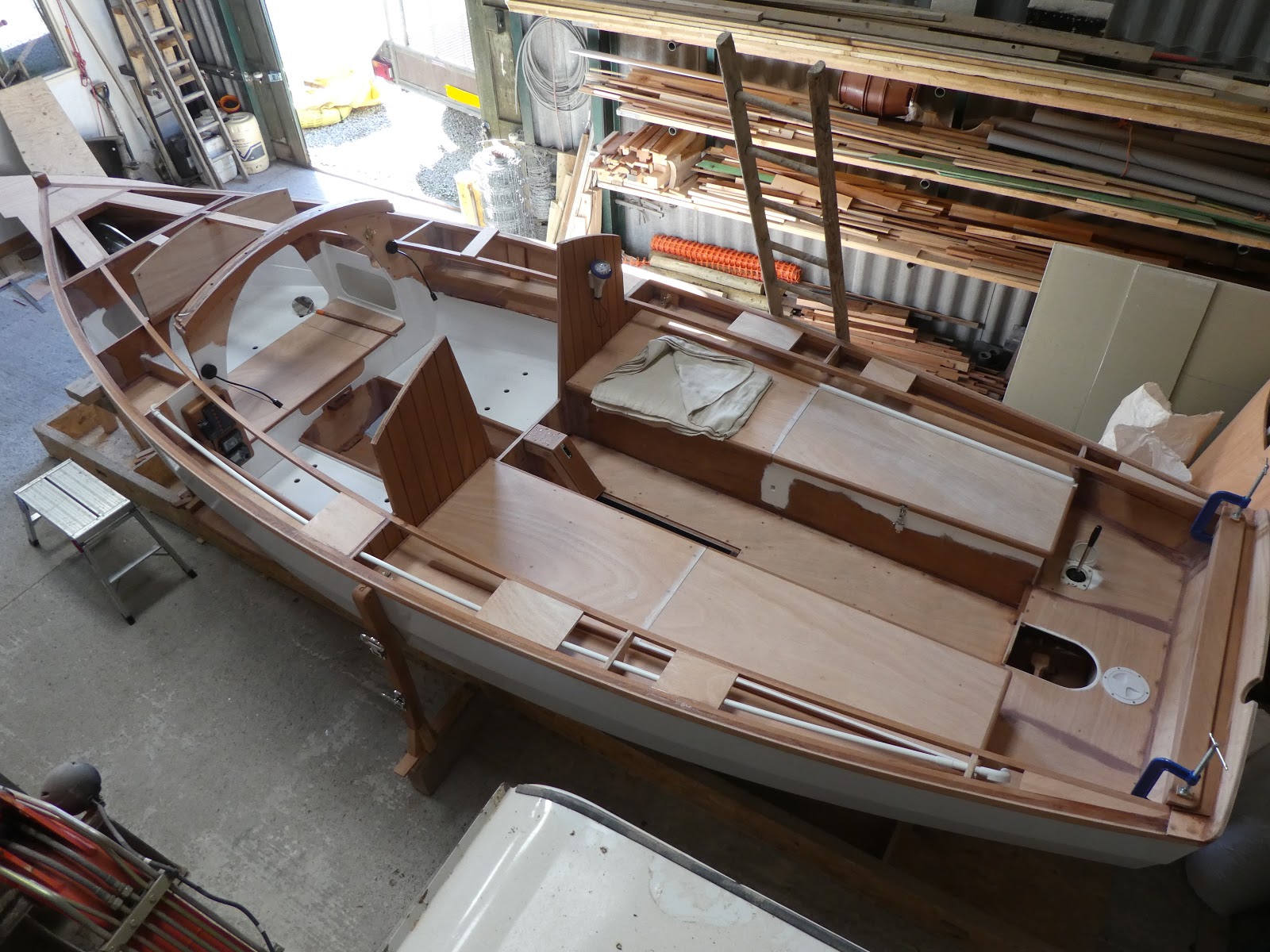
I have previously alluded to my intention to finish the decks in teak planking, to maintain continuity throughout, I have applied the same treatment to the cockpit sole.  Firstly, to stiffen and make water tight, I sheathed the whole area in 300 gsm woven cloth saturated through with epoxy. The teak planking I purchased some months ago is supplied from stock at 45mm wide. To maintain full width boards across the width of the cockpit, I fitted hardwood skirting’s down the sides, machined at the appropriate thickness to achieve perfect spacing. I cut a taper at the aft end to prevent interference with the drainage holes. 

I cut and dry laid the teak to the whole area using 5mm plastic tile spacers, to provide accurate spacing for the caulking, before gluing down in a bed of epoxy. It was very difficult working both within a confined space and down in the well, all had to be done by kneeling on the locker covers and reaching down, not the best position to be working in. To minimise cleaning up, I decided to apply masking tape to the surface of the teak then all joints were primed with Sika DC caulking primer before being filled with Sika 290DC PRO Deck Caulking. I pulled off the masking tape as the Caulking began to skin up which proved to be a tricky job but saved a lot of mess on the surface. I left it for a couple of weeks before sanding off to finish. On the whole this was a difficult and time consuming job but I think well worth it, producing a great looking, practical and hard wearing surface. I also made the centre board cap from teak which was dry fixed by bronze screws; the joints were left un-caulked to allow for removal before the fitting of the centre board, this I plan to do after the boat has been taken outside during the final fitting stages.


The teak planks dry fitted and set out with plastic tile spacers. Note the taper cut into the aft of the skirting’s to allow unobstructed drainage to the engine well.


Sanded and finished.

I have also taken delivery of the fittings, some of which were purpose made. I agonised for months about whether to use bronze or polished stainless steel. Eventually I made the decision to use bronze which I believe to be correct, I think the hardware looks stunning and will be even better when fitted to the boat. Note that the Tabernacle is manufactured in stainless steel as specified by the architect; the only other specified alternative material for this item was galvanised steel.


Other work commitments continue to frustrate the build, therefore progress has been sporadic. Any available free time has been dedicated to the project achieving some limited progress, including work manufacturing and fitting rubbing strips, the cabin roof and coamings etc. all of which will be the subject of my next post.  

Monday, 27 August 2018

Engine and Mounting


Over the months of July and August, very little work on the build has been undertaken due to other commitments and holidays, all very frustrating. This frustration was further compounded by the extraordinary difficulty experienced in purchasing an outboard motor! Chandlers within a reasonable distance from my location, either ignored my requests to submit quotes, or in the case of the eventual supplier, took my money then failed to supply the goods, resulting in me having to re-claim the funds through the credit card company. However, following almost three months of phone calls and emails I did finally managed to purchase the engine and ancillary equipment, although the whole experience soured the project to some degree.

The architect specifies a maximum engine power of 10 hp but suggests that 3 to 5 hp is sufficient for this light boat. Because of space limitations within the outboard motor well and the dimensions of the hull aperture through which the motor will project, I decide to purchase either a Honda BF 5 or a Yamaha F5, both having very similar specifications. I have previously mentioned that I intend to sail the boat around the Scottish Hebrides which are in parts subject to strong tidal streams. I therefore decided to purchase a 6 hp Yamaha F6c to deliver that little extra power; the 4, 5 and 6 hp motors in this range are all of the same external dimensions and weight so the bigger engine did not have any impact on the space considerations. I also opted for a charging coil which delivers a 12V 6A power supply to charge the battery plus a 25 litre remote fuel tank complete with delivery line to extend my operating range.

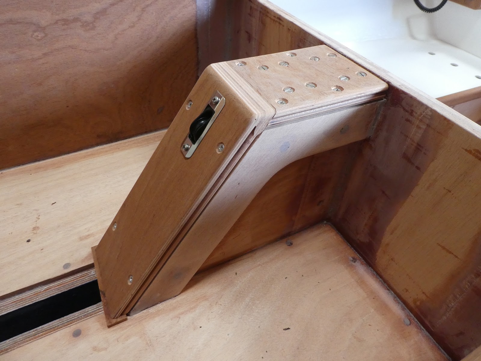
The architects design states that two hardwood blocks are to be fitted either side of the bulkhead forming the forward face of the engine well, cut on an oblique angle to achieve the correct motor trim. Before gluing I fitted the motor to make sure everything was correct but noticed that there was a degree of flexibility in the plywood bulkhead. To rectify this situation I manufactured a foot extending down to the cockpit floor and out laterally to terminate at the drainage holes. To further strengthen the joint between the block and the foot I tongued and grooved the two together, then applied an epoxy fillet at the junction between the different components and the bulkhead. I also recessed the aft engine well block and inserted two stainless steel plates to provide a wearing surface for the engine clamp face. This assembly produced an immensely strong and rigid structure.


The reinforcing foot inside the cockpit. This will be further strengthened by the abutment of
 the teak planked cockpit floor.


Stainless steel plates fitted to the wearing surface of the aft face of the hardwood block.


The Yamaha F6c sitting snug and unobtrusively in its well.

Monday, 30 July 2018

Mast Assembly


We have been experiencing a heat wave here in the UK which has greatly improved the viscosity of the epoxy and therefore its ability to penetrate the timber surfaces being glued. I have assumed that the mast will be subject to considerable forces in all directions and as such its structural integrity is paramount, I therefore saw this as an opportunity to construct the mast whilst the conditions were favourable. Rounding off and finishing can be done at a later date.

The architect recommends Douglas fir as a suitable species of timber for the mast and spars. Following prior consultation with my local timber merchants, I managed to obtain some top quality stock, perfectly true with a clear straight grain. I purchased sufficient for the whole job.

Handling 6 metre lengths of timber by oneself proved a little tricky, but I have a number of roller stands which proved essential. Four boards make up the laminated mast which I cut and planed dead true. Approximately three quarters of the mast is a hexagonal hollow. Because I have opted for navigation lights, VHF radio etc. I had to build in a duct/conduit to carry the cables to the mast head with the ability of pulling cables through at a later date if required. Through the solid sections I machined a 7 mm radius half round groove in each half then installed a plastic conduit supported in small plywood cradles down the centre of the hollow section. I was particularly careful to ensure there were no square edges to avoid any potential snagging during the process of pulling the cables through. During the gluing process I inserted a draw cord, when the mast was fully clamped up I tied a small piece of towelling onto the cord and pulled it through several times to remove the excess epoxy that had squeezed out into the duct. I continued this process at intervals during the curing time to be certain that the duct remained clear.


I have decided to terminate the cable duct just above the level of the Tabernacle. You can see that I have machined it in a slow curve to enable an easy cable pull through.


Note that I have recessed the plastic conduit into each end of the hollow section then rounded off the shoulder to prevent any snagging of the cables when pulling through.


Thursday, 19 July 2018

Painting and Deck Fixing

It was necessary to paint as much of the boat as possible before the decks were fitted. As previously stated, many of the areas are difficult to access even before the plywood deck is fitted. I under estimated the cost of the painting materials and the time required to apply it, this proved to be both a costly and time consuming job to achieve the standard that I required.

I have used Hempel paints throughout the whole build. The coating regime for the internal painting began by applying Wood Impreg as a sealant, three coats of Primer Undercoat then three coats of Brilliant Gloss for visually exposed surfaces or three coats of Bilge and Locker paint where appropriate. I rubbed down de-dusted and cleaned between each coat. Sapele trims and other exposed hardwood items were sealed, again using Wood Impreg, before finishing with multiple coats of clear varnish. All the paint and varnish was applied with a range of specialist brush’s and roller, before laying off with a brush to finish.

The plywood deck panels were glued with epoxy and screwed down with countersunk stainless steel screws; any excess epoxy squeezed out below was removed and cleaned down with disposable paper towels. These areas will then only require a light rub down and the paint touching up. The screw heads were filled with epoxy filler. When set, the whole deck was rubbed down by an orbital sander to remove any irregularities whilst paying particular attention at the joints. The overhanging waste was trimmed back flush with the planking then a small pencil round radius was routed onto the corner. The whole deck was then sheathed in 300 gsm woven cloth and lapped over the edge onto the planking by approximately 30 - 40 mm. The small radius cut onto the top edge allowed the cloth to be dressed tightly over without any air pockets forming.


The areas to be glued were masked off before painting the underside of the deck boards.


The wiring has been installed whilst most areas are still relatively reasonably accessible. All cables and fittings are to specialist marine standards. The fixing brackets were fitted to the wiring conduit before the deck boards were fixed down, these will be stuck to the underside of the deck with self-adhesive double sided pads.

Tuesday, 17 July 2018

Deck, Supporting Carlin’s and Beams

There has been a considerable amount of work that I felt was necessary to be carried out before the deck can be fixed in place. Carlin’s, beams and doublers act as support and reinforcement below the deck and inside the hull, and will allow additional strength for bolted through fittings, all these small but important items have required manufacture and fitting. Furthermore many of the areas are difficult to access particularly for painting, it’s therefore advisable to prepare and paint as many areas as possible before fixing the deck down.


Carlin’s, beams and reinforcing doublers all fitted and glued into place. The doublers are mainly 20mm thick laminated from two 10mm pieces of plywood. This reinforcement has been added to allow fittings to be bolted through, cleats, sheet leads, chain plates etc. There are also doublers beneath the butt joints of the deck.


I also prepared and dry fitted the whole deck plus the trim on the transom. I marked around the timbers below the plywood deck sections before removal, this allowed positioning of masking tape over the fixing areas to prevent contamination whilst painting the boards before fixing.  I took the opportunity of shaping the trim at the aft of the cockpit and inserted a central inlaid feature, deliberately cut from a different board of sapele to obtain a contrasting colour and grain structure, I further highlighted this with an inlay of ash around its perimeter to achieve further enhancement.

I have decided to finish the deck in teak planking set in epoxy with black Sikaflex joints. To assist in the design of the layout, I set out the planks in chalk to one half of the boat, this proved very useful to calculate the amount of planking required and was an easy way to alter the design by simply rubbing off the chalk with a damp sponge, I was then able to develop the set out until arriving at the most appealing design.


 Ash inlay, again as previously mentioned, as a nod to the tree I felled which has been used in the build.


Deck planking marked out in chalk


I decided to reinforce either side of the centre board case creating a broad edge for a more secure fixing for the capping’s. I laminated up two 10mm pieces of plywood then cut them to the shape shown in the photograph before gluing to the case. The capping’s I made from laminating two 10mm pieces of hard sepele faced plywood, then machined a bead in the edge to aesthetically improve junction with the case.


 Reinforcing pieces either side of centre board case and capping. The centre board hoisting system provided by Harken blocks mounted within the case have been fastened with stainless steel bolts which, will allow removal for future maintenance. These were removed before painting.


To accommodate an anchor of sufficient holding capability that would fit into the restricted space of the mooring and stowage well, proved to be an item of extensive research. I looked at every anchor design on the market and found that most would simply not fit, until I came across the Plastimo Kobra folding anchor. Research of this product revealed it to be an ideal solution, the folding capability allowed easy stowage with room to spare. Because of this I was able to raise the forward base of the well by around 50mm to allow better drainage towards the oblique to aft drilled holes through the hull planking, this also gave more room below. I sourced some small stainless steel shell vents to provide cover to the exposed holes on the outer face of the hull which looked very neat. The bottom of the well was filleted around its perimeter, sheathed in 300 gsm woven glass fabric saturated in epoxy, filled and faired to a smooth finish. Its planned to fit a protective rubber mat to the bottom minimise potential damage from the anchor and chain.


The Plastimo Kobra folding anchor neatly stowed in the well. The additional 20mm thick plywood reinforcing seen here beneath the deck, will provide solidity for bolted through fixings for mooring cleats, stemhead chain guide, bowsprit iron and lashing eye plates. You can also see the anchor cable fastening eye bolt.


The stainless steel shell vents can be seen covering the anchor and mooring stowage well drainage holes


Sunday, 11 March 2018

Manufacturing items in the workshop


The first anniversary of the start of the build has just recently passed. I began 12th February 2017 and up to 11th February 2018 the work has consumed 959 hours.

During the recent past depths of winter, when we experienced occasional extremely cold temperatures, I decided to cease using epoxy on the hull with the exception of some minor gluing, undertaken only on the mildest of days. I have instead mainly been focused on manufacturing smaller items in the workshop, of which there are plenty, in fact more than enough to keep me busy for the duration of the cold weather.

The construction of the rudder is one of the many items that I placed to one side for this planned period in the workshop. I noticed from the blog of another builder of Beniguet, that he had encountered problems with the rudder whilst underway, the plywood cheeks either side of the tiller mortice had failed under stress. I realise that as opposed to a design weakness, this may have been caused by a collision which, could have applied the excessive force’s necessary to cause the failure. Nonetheless, based on his experience, I considered it might be prudent to reinforce this area. I plated either side of the cheeks in 316 stainless steel by spanning the mortice then bolting through with stainless steel bolts. I shall paint this as the rudder to minimise the visual impact. The drawing shows a small cleat for locking off the rudder blade hoisting line. I was unable to source anything of this size at any chandlers so I manufactured one from some oak stock.


I began the build by manufacturing the tiller and can now see how it looks when mounted in its mortice.


I constructed a jig to manufacture the coach roof and companionway sliding hatch. Although not an inconsiderable structure in its own right, it was well worth the effort, allowing for a relatively straightforward process of bending and gluing the layers of plywood together. After the lamination and set, the coach roof was removed, additional packing pieces of the appropriate thickness were fixed to the jig in order to maintain the correct radius for the companionway hatch. Both were then filled and rubbed down to achieve an excellent result. 


Within the cabin beneath the mast tabernacle, fixed either side of bulkhead 4, the drawings show two 60mm x 20mm beams glued tight up to the coach roof. I increased these dimensions to 60mm x 40mm to allow me to machine a groove in the upper edge to insert plastic conduit which will contain cables for cabin lighting, navigation lights and the coax cable for the VHF radio. To minimise the impact of these beefed up beams, I machined an ovilo radius-ed moulding onto the lower edge which, should look quite attractive when the sapele is clear varnished along with the inner face of the house coamings.


The beefed up beams either side of bulkhead 4 showing the grooves and conduit machined into the top. You can also see the cable conduit that will run beneath the deck all the way to the stern.


I greatly increased the specification of the folding table by rebating the Sapele faced plywood top into a solid timber frame. I inserted a 2mm thick inlay between the two for aesthetic reasons, also as a nod to the home grown ash I have used to manufacture the tiller. To enable use of this table in the cockpit during fine weather, I designed and constructed a hardwood base frame with locating sockets for the legs. The whole assembly is manufactured from Sapele which I shall finish in clear varnish.


Before starting the build there were a number of aesthetic design alterations I had decided to make, one of which was the panelling of the aft face of bulkhead 3. These are individual 5mm thick boards machined with an edge chamfer to produce a v-groove when butted and glued together.


Drying legs with stainless steel folding steps fitted to one side.


Sliding hatch. Note the drip groove machined beneath the aft edge to prevent water tracking back into the cabin, also the finger purchase for closing from within.


Many other items and trims have been manufactured ready for use at a later stage, including the assembly of the companionway panels. I have also spent a considerable amount of time researching various fittings and other products, sourcing and purchasing timber for the Mast, Spars, Oars and the teak decking.


Thursday, 1 February 2018

Electronic Equipment and Wiring


My intention is to sail on Europe’s Atlantic edge, the Scottish Western Isles of the Inner and Outer Hebrides, an archipelago comprising hundreds of islands surrounded by potentially challenging waters. It’s therefore my intention to equip the boat with a VHF radio fitted with an internal GPS, navigation lights, Tacktick speed and depth gauge, GPS chart plotter, cabin lighting, USB charger, battery monitor and an outboard motor fitted with a 12v 6amp power supply for re-charging the battery/batteries. All lighting units are LED’s to limit the draw on the battery. As I have already previously mentioned, this equipment has had to be considered at this stage of the build because once nearing completion some areas will be difficult or impossible to access, I also want a very neat final finish with no visible surface fixed cables. I have designed and constructed a compact but adequate control panel from sapele which I intend to finish in clear varnish. This is fitted to bulkhead 4 above the port side berth. I had to cut an aperture in the bulkhead to accommodate the radio which projects slightly into the storage area beneath the lateral shelving between bulkhead 4 & 5. I have constructed an easily removable rear cover to protect the wiring from items that may be stored in this locker. The chart plotter, speed and depth gauge will be mounted on the aft face of bulkhead 3, enabling accessibility and visual monitoring from the cockpit.


Radio and other equipment fitted to the control panel. These will be removed
 before varnishing and painting. The radiused insert in the side locker opening
 below the lateral shelf, is the outer face of the rear wiring protection cover.


All hidden cable runs will be contained in 20mm diameter white plastic conduit. I propose to manufacture purpose made timber capping to hide potentially visible cable runs in the cabin area; these will then be painted in the same colour paint as surrounding areas to limit their visual impact.